Use app×
Join Bloom Tuition
One on One Online Tuition
JEE MAIN 2025 Foundation Course
NEET 2025 Foundation Course
CLASS 12 FOUNDATION COURSE
CLASS 10 FOUNDATION COURSE
CLASS 9 FOUNDATION COURSE
CLASS 8 FOUNDATION COURSE
+3 votes
455k views
in Physics by (51.7k points)
closed by

Draw a schematic diagram of a circuit consisting of a battery of three cells of 2V each, a 5Ω resistor, an 8Ω resistor, and a 12Ω resistor and a plug key, all connected  in series.

2 Answers

+3 votes
by (266k points)
selected by
 
Best answer

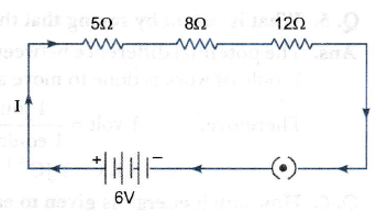
It is noted that the ammeter has been put in series with
the circuit and the voltmeter has been put in a parallel with12Ω  resistor.
(i) Calculation of current reading in the ammeter:

(ii) Calculation of potential difference reading across 12

Ω resistor. 

Current,I=0.24A,Resistance,R =12Ω, Potential difference,V =?
Applying Ohm's law
v = IR= 0. 24 x 12= 2.88 V
Therefore, the voltmeter reading is 2.88 V.

+2 votes
by (17.0k points)

Three cells of potential 2 V, each connected in series, is equivalent to a battery of potential 2 V + 2 V + 2 V = 6V. The following circuit diagram shows three resistors of resistances 5 Ω, 8 Ω and 12 Ω respectively connected in series and a battery of potential 6 V.

Welcome to Sarthaks eConnect: A unique platform where students can interact with teachers/experts/students to get solutions to their queries. Students (upto class 10+2) preparing for All Government Exams, CBSE Board Exam, ICSE Board Exam, State Board Exam, JEE (Mains+Advance) and NEET can ask questions from any subject and get quick answers by subject teachers/ experts/mentors/students.

Categories

...