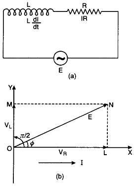
Let an inductance L and resistance R be connected in series to a source of an alternating e.m.f. E as shown in Fig. (a).
The alternating current I at all points in series circuit has the same amplitude and phase but the voltage across each element will be of different amplitude and phase.
(i) If VR is the voltage across R, then
VR= IR
Voltage across the resistor is in phase with current
(ii) If VL is the voltage across, then
VL = I XL
Voltage across the inductor leads the current by a phase π/2.
Let us construct the phasor diagram for this circuit. A single phasor I is used to represent the current in each element and VR and VL represent voltage phasors. If VR is represented along OX by OL, (current is also along OX) then VL will be along OY by OM because VL leads the current I by a phase π/2. This is graphically represented in Fig. (b).The resultant of VR and VR is represented by E and makes an angle Φ with current I.
From the phasor diagram, we find that

where ZL = \(\sqrt{R^2+\omega^2 L^2}\) is the effective opposition offered by L and R and is called impedance of LR circuit . Since Φ is the angle made by the resultant of VR and VR with X-axis, so from phasor diagram, we have
tan Φ = \(\frac{LN}{OL} =\frac{OM}{OL} = \frac{V_L}{V_R}\)
= \(\frac{IX_L}{IR}\)
= \(\frac{X_L}{R} = \frac{\omega L}{R}\)
or tan Φ = \(\frac{\omega L}{R}\) ..........(2)
Equation (2) gives the phase angle Φ, by which alternating e.m.f. (voltage) leads the current in an LR-circuit.


