AC generator consists of the four main parts:
(i) Field Magnet: It produces the magnetic field. In the case of a low power dynamo, the magnetic field is generated by a permanent magnet, while in the case of large power dynamo, the magnetic field is produced by an electromagnet.
(ii) Armature: It consists of a large number of turns of insulated wire in the soft iron drum or ring. It can revolve round an axle between the two poles of the field magnet. The drum or ring serves the two purposes: (i) It serves as a support to coils and (ii) It increases the magnetic field due to air core being replaced by an iron core.
(iii) Slip Rings: The slip rings R1 and R2 are the two metal rings to which the ends of armature coil are connected. These rings are fixed to the shaft which rotates the armature coil so that the rings also rotate along with the armature.
(iv) Brushes: These are two flexible metal plates or carbon rods (B1 and B2 ) which are fixed and constantly touch the revolving rings. The output current in external load RL is taken through these brushes.
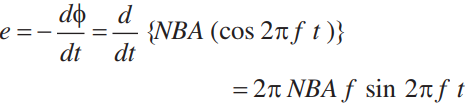
Principle: When the armature coil is rotated in the strong magnetic field, the magnetic flux linked with the coil changes and the current is induced in the coil, its direction being given by Fleming’s right hand rule. The direction of current remains unchanged during the first half turn of armature. During the second half revolution, the direction of current is reversed. Thus, the direction of induced emf and current changes in the external circuit after each half revolution. If N is the number of turns in coil, f the frequency of rotation, A area of coil and B the magnetic induction, then induced emf